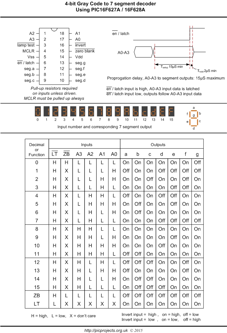

Only con is that we will require an inexplicable amout of jumper wires. Using the same code mentioned above we can use two and up to four, Seven segment display countdown. Now there is an interesting breadboarding technique that can be used in this particular project. On(num0) // Passing “num0” to the function “on()” defined above to display “0”ĭelay(500) // Delay for 1 second to see the “0” PinMode(A, OUTPUT) // Making all pins outputs Result = bitRead( num, 1) // Same thing for the 6 remaining segments. If (result = 1) // Check to see if this segment should be on. Int result = bitRead(num, 0) // Read the first binary entry in num and stores it in result. Void on(byte num) // This function turns on the correct pins to display numbers passed to it // through the variable “num”. Int C = 4 // DOT is pin 5, not used in this example.īyte num0 = 0x3F //Hexadecimal format based upon the A-G, 0-9 Chart in excel and the wiring // of the segment (refer to the on/off table image below). Int A = 7 //Defines all pins on the Arduino Uno board in order of connection. We are all done with assembling the circuit.

In likewise fashion we will jconnect the second to the third pin slot in arduino. Firstly we will start by connecting the first pin on the seven segment display to the 2nd pin in the arduino.

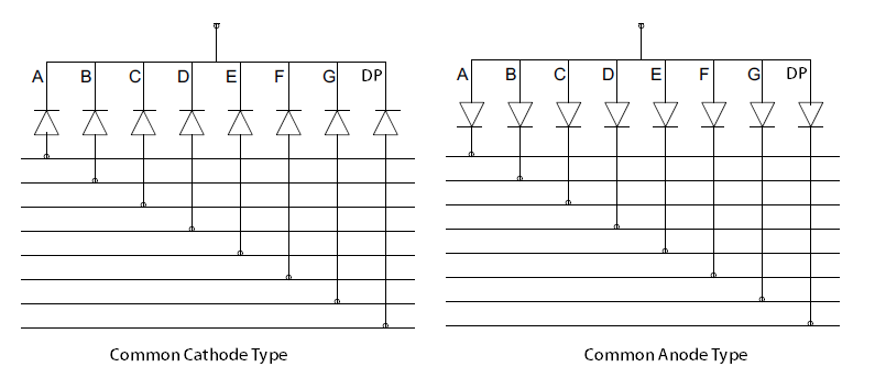
An additional 8th LED is sometimes used within the same package thus allowing the indication of a decimal point, (DP) when two or more 7-segment displays are connected together to display numbers greater than ten.įor now we will use a common anode seven segment display. Each of the seven LEDs is called a segment because when illuminated the segment forms part of a numerical digit (both Decimal and Hex) to be displayed. The 7-segment display, also written as “seven segment display”, consists of seven LEDs (hence its name) arranged in a rectangular fashion as shown.

The main advantage of light emitting diodes is that because of their small die size, several of them can be connected together within one small and compact package producing what is generally called a 7-segment Display.


 0 kommentar(er)
